


Electric motors are fundamental to modern technology, powering everything from household appliances to industrial machinery. Brushed DC motors, with their robust design and straightforward speed control, are particularly popular in many applications. However, to leverage these qualities effectively in projects, understanding how to manage their speed is crucial. In this article, we’ll guide you through the process of making a brushed motor speed controller – an essential device for hobbyists and engineers alike that allows for precise adjustment of motor operation to match the needs of various applications.
Understanding the Basics of DC Motor Speed Controllers
A DC brush motor controller is a specific type of electronic circuit designed to precisely manage the rotation speed of brushed DC motors. It functions by adjusting the voltage that reaches the motor, using strategies such as Pulse Width Modulation (PWM). This control ensures that users can vary the motor’s speed with precision, allowing for fine adjustments to the motor’s power output based on the task at hand.
With the ever-growing need for remote operation, incorporating features like a remote kontrol motor function into a brushed motor controller can significantly enhance the usability of motor-driven devices. Such enhancements allow for wireless speed adjustments—ideal for applications requiring control from a distance, like in certain automated systems or hobbyist remote-controlled models.
The two main types of controllers you might encounter are analog and digital. Among these, a digital brushed motor speed controller, often using PWM, tends to offer greater precision and efficiency. These advantages make digital control techniques preferred in applications where exact motor speed regulation is essential for performance.
Tools and Materials Needed
Gathering the right components and tools is the first step toward constructing a robust brushed motor speed controller. Below is a foundational list of materials you may need:
- PWM speed control circuit specifically designed for brushed motors
- Brushed DC motor
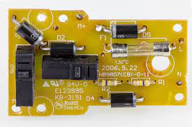
- Breadboard or PCB (Printed Circuit Board)
- Soldering iron and solder
- Wire cutters and strippers
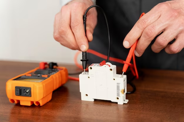
- Multimeter for testing and troubleshooting
The accuracy of your project can be significantly affected by the quality of tools at your disposal. It is vital to use quality tools for a smoother process and to use a multimeter to diagnose any issues within the dc brush motor controller as you progress.
Step-by-Step Guide to Constructing a DC Motor Speed Controller
Building a brushed motor controller is not just about connecting components; it’s about understanding the purpose of each part and ensuring they come together in harmony. Here are the essential steps to build your controller:
- Design or choose a proven circuit schematic for a brushed motor speed controller
- Gather and prepare all required components
Your circuit diagram serves as a roadmap for your project’s journey. Whether you are following an existing schematic or taking on the challenge of creating a customized design, ensure that every component and their connections are well-defined. For beginners, following a well-tested schematic can save a lot of time and headaches.
After preparing your design, organizing your components is the next phase. For those who want to test the setup before making any permanent changes, using a breadboard is recommended. It provides a great platform for a trial assembly of your brushed motor controller, giving you the flexibility to make adjustments as needed.
Consider the following table layout for a simple PWM DC motor speed controller:
| Component | Quantity | Purpose |
|---|---|---|
| PWM IC | 1 | Generates PWM signals for the controller |
| Resistor | Several | Limits current and defines frequencies |
| Capacitor | Several | Stabilizes voltage fluctuations |
| Diode | 1 | Prevents the motor from receiving reverse current |
| Potentiometer | 1 | Allows for manual speed adjustments |
| Transistor | 1 | Amplifies PWM signals to control the motor |
| Brushed DC Motor | 1 | The motor that will be controlled |
When you’re satisfied with the breadboard assembly, transfer the layout to a PCB to begin soldering the components in place. Clean and secure solder joints are crucial to the functionality of the motor speed controller, ensuring that all connections are reliable and robust. After your meticulous soldering, allow the joints to cool before running any tests to avoid damaging any sensitive components.
Testing and Troubleshooting
Once you’ve completed the assembly of your brushed motor controller, it’s time to put it to the test. Begin by providing power to the circuit and gradually adjusting the potentiometer to control the speed of the DC motor. Keep an eye on the motor’s behavior; it should respond smoothly to changes in the potentiometer’s position. A multimeter can be a valuable asset at this stage to verify that the voltage levels and current at various points in the circuit match your expectations.
If you encounter any problems, like the motor not responding or erratic behavior, don’t panic—troubleshooting is part of the learning curve. Here’s a quick list to guide you through common issues:
- Check that all connections are secure and that components are properly soldered to the PCB.
- Ensure that the power supply is adequate and stable for the motor’s requirements.
Remember that sometimes issues may arise from a malfunctioning component. Replacing parts one at a time can isolate the faulty piece. Additionally, it’s crucial to confirm that the PWM signal from the controller is accurate and consistent, which can be done using an oscilloscope or a similar diagnostic tool.
Enhancing Your DC Motor Speed Controller
After testing and confirming that your basic brushed motor speed controller is working, you might consider upgrades that can enhance its functionality. These enhancements can range from adding a heat sink to the transistor to prevent overheating, to incorporating a digital display that shows real-time speed data. For those interested in remote operation, integrating a wireless module could take your controller to the next level, allowing you to adjust your motor’s speed from a distance.
Here are some potential upgrades you might want to consider:
- Integrating a feedback loop that uses sensors to adjust the motor speed automatically in response to varying load conditions.
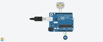
- Implementing a microcontroller-based design, which offers better control, customization, and the possibility for programming complex behavior.
These additions not only refine performance but also give valuable learning experiences in advanced electronics and programming. And as you grow more comfortable with these concepts, you might find yourself designing custom speed controllers for specific applications.
Conclusion
Crafting a brushed motor speed controller can be a rewarding project that combines electronics knowledge with practical skills. Whether you’re a hobbyist looking to personalize your remote-controlled car or an engineer focused on precision machinery, understanding DC motor control is a valuable asset. The process reflects a harmonious blend of theory, craft, and troubleshooting that can be adapted and expanded upon based on your needs.
Remember that the key to success is patience, practice, and persistence. As with any complex task, you’re likely to encounter challenges along the way, but each problem you solve will further your understanding and abilities. Your homemade brushed motor speed controller is not just a tool; it’s a reflection of your skill and learning journey.
FAQs
- Can I use this speed controller for any brushed DC motor? This design is versatile and can be adapted for most brushed DC motors. However, you must ensure the controller matches the motor in terms of voltage and current capacity.
- What can I do if the motor doesn’t change speed smoothly? If the motor’s speed isn’t adjusting smoothly, double-check your potentiometer and the PWM signal for any inconsistencies. Also, ensure your power supply is stable.
- Is there a way to reverse the direction of the motor with this controller? To reverse the direction of the motor, you’ll need to incorporate an H-bridge into your design, which allows you to control the direction of current flow through the motor.
- How can I add a remote kontrol motor function to my speed controller? Adding remote control functionality typically involves integrating a wireless receiver into your design and linking it to the speed control input, allowing you to adjust it remotely.
- Why is my motor overheating when using the controller? Overheating can occur if the motor is running at high loads for extended periods or if your speed controller design doesn’t incorporate proper heat dissipation for the power-transferring components like transistors. Adding a heat sink or reviewing your current ratings can help mitigate this issue.